Personnel
PhD Student Brian Sveistrup Jensen
Associate Professor Tom Keinicke Johansen
Period
June 2009 – May 2012.
Funding
The project is internally funded by DTU Elektro.
Background
The first experimental results of using microwave instruments, e.g. radar and radiometers etc. for detection and monitoring of human vital signs like heartbeat and respiratory activity was published in the 1970s. Since then, numerous publications have treated this subject in order to establish the fundamental theory and to test the viability of such a non-contact vital signs instrument. The applications are many. Here only two of such applications are listed:
-
Monitoring of patients at hospitals without being in contact with them. This means that patients can move freely within the sight of the instrument and, that electrodes for the purpose of monitoring heartbeat and respiratory activity can be omitted. This would ease everyday life for both patients and hospital staff greatly.
- For detecting the presence of a living person in visually obstructed areas like those hit by earthquakes where buildings have collapsed and buried the person in debris. Opposite many of the conventional instruments for this purpose, a microwave based vital signs instrument, will be able to see through the debris and still detect the living person.
The human respiratory and heartbeat movement is relatively slow and thus require state-of-the-art phase-noise, 1/f-noise and/or ultra-wide-band (UWB) performance in order to obtain a high dynamic range instrument with a high probability of detection. Many microwave instruments reported so far have been built for research purposes only (i.e. a test setup in a laboratory using commercial available components) and/or still suffer from a bulky design, high power consumption or poor probability of detection. However, recent advances in MMIC production technologies and design methodologies have created the opportunity to design ultra low phase-noise, low power and low cost instruments for use in everyday life at hospitals and rescue workforces around the world. These advances have not yet been exploited for the design of a compact high-dynamic range state-of-the-art phase-noise performance vital signs detection and monitoring instrument.
The PhD project includes one or more of the following research areas:
- Design and system level analysis of high dynamic range, low phase noise radar architectures.
- Design and testing of low phase noise and low 1/f noise MMIC components.
- Design and characterisation of high dynamic range mixers.
- Characterisation of the vital signs response obtained from investigating a living human body by use of radar instruments.
- Advanced Testing at instrument-level using special signal processing for obtaining and analysing the desired responses.
Description
Measuring human vital signs with the use of radar is a matter of measuring the small movements on the chest wall due to the respiration and heart beat activity. These movements can typically be characterized as follows:
- Heart Beat Activity: 0.01–0.1 mm movement with a rate of 60–170 bpm (1.0-2.9 Hz)
- Respiration Activity: 1–3 mm movement with a rate of 10–40 bpm (0.17-0.67 Hz)
These two movements are placed on top of each other and needs to be separated by the vital signs instrument.
A continuous wave (CW) signal, transmitted by a CW radar, that hits a stationary object, will be reflected and returned to the radar with the same frequency and a constant phase due to the constant distance (and thus number of wavelengths) to the object and back. If the object is moving with a constant speed toward or away from the CW radar, the transmitted signal will be compressed or decompressed, respectively, a phenomenon known as the Doppler Effect. The net result is a reflected signal with a different frequency than that of the transmitted one – an effect used for measuring speed of objects.
If however, the object is moving with a net zero displacement but in a periodic manner back and forth compared to the CW radar, the returned signal will have a net frequency equal to the one transmitted but with the phase modulated by the same rate as the object movements. By transmitting a microwave signal towards the human chest wall, a CW radar is thus able to detect the movements due to respiration rate and heart beat activity.
One of the major challenges for such an instrument is that the chest wall movements have frequencies very close to zero frequency, so the modulation of the transmitted signal (carrier) will place the desired signals very close to the transmitted frequency where phase noise is very high.
A block diagram of a simple CW radar is shown in figure 1. As can be seen, part of the transmitted signal (local oscillator, LO) is used to down-convert (mix) the reflected signal to base-band. As the transmitted and reflected waves originate from the same source, they are correlated and so is the phase noise for each signal. The net result on the base band signal after down-conversion is that the phase noise is converted to DC – or in other terms, filtered out. However, as the distance to the target increases the amount of correlation between the transmitted and reflected signal decreases, which means that this filtering effect will decrease and thus the signal-to-noise ratio (SNR) will worsen. For systems of moderate phase noise performance, this range-correlation effect severely degrades already at a couple of meters to the target. It is therefore essential to the system that the components and especially the signal source have very low phase noise. Furthermore, as the system relies on the range-correlation effect, it is important that it is very simple and do not introduce too much of a time delay (phase shift) in electrical part of the path from the source to the target and back to the receiving mixer.
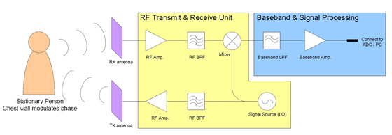
Figure 1:
Functional block diagram of a CW radar used as a vital
signs detection and monitoring instrument
In general; for higher frequencies the sensitivity goes up because the chest wall movement becomes larger compared to the wavelength of the transmitted signal, i.e. the phase is modulated with greater amplitude. However, because the desired signals are located on top of each other, inter-modulation (IM) occurs between the signals. For higher frequencies the IM becomes stronger and at some point the IM products become comparable to the desired signals, thus making it difficult to distinguish between the different frequency components. Furthermore when IM occurs, the desired signal strength goes down as power is used for the IM-tones instead. This inter-modulation effect has been simulated with Agilent ADS, see figure 2. It can be seen that for low frequencies the strength of the desired signal increases as the transmitted frequency increases. However, at some point IM occurs and the strength of the desired signal goes down, as described above. The point at which this occurs depends upon the amplitude of the chest wall movement due to the respiration activity. Thus an optimum exists for which the signal strength peaks. As seen from the figure, this optimum is at some 20 to 26 GHz.
The PhD project concerns the development of a small single-chip radar solution that can be used for high-sensitivity measurements of human vital signs. The radar front-end (RF Transmit & Receive Unit in figure 1) and part of the base-band circuitry is to be integrated in a Complementary Silicium Germanium (SiGe:C) Heterojunction Bipolar Transistor (HBT) technology as it offers high level of integration, low phase noise and low power operation. All base-band signal processing will be carried out externally on a computer with appropriate signal processing software.
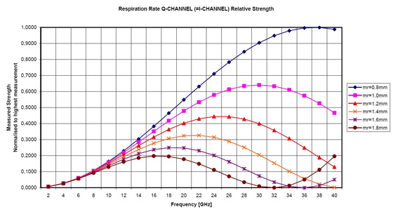
Figure 2:
simulation af the inter-modulation effect that occurs in a vital signs radar.
The movement due to heart beat is assumed to have an amplitude of 0.08 mm
while that for the respiration activity (mr) is swept from 0.8 mm to 1.8 mm
[Back to Research projects]