Personnel
Ph.D. student Vitaliy Zhurbenko Professor Viktor Krozer (supervisor) Associate Professor Peter Meincke (co-supervisor)
Period
September 2005 – August 2008
Funding
Technical University of Denmark.
Background
As part of the project Microwave Imaging for Breast Cancer Detection a microwave camera is to be constructed. The microwave imaging is one of the most perspective methods, which can replace Ionizing Radiation technologies like X-Ray imaging and improve detection and characterization of breast tumors. Over the past several years, significant progress has been made on the development of imaging systems for breast cancer detection based on nonionizing electromagnetic waves. In the next decade, research will be focused on the development of microwave systems to provide a viable diagnostic option for many patients.
The research and development of this technology for medial applications are facing significant difficulties. One of the difficulties includes a high attenuation of the electromagnetic field within the body. Attenuation is less at lower frequencies, but the spatial resolution is lower. Another difficulty is caused by the anatomical features of the objects; this case has to be referred to the tomography with a limited angle of observation. Existing systems for microwave breast imaging can only produce two-dimensional images with low resolution.
Description
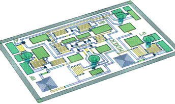
This project aims at the development of a tomographic system exploring an approach to three-dimensional microwave imaging based on inverse scattering, in which several microwave transmitters illuminate an object and scattered fields in numerous locations are measured. A configuration of the microwave camera is based on individual signal processing units (Fig. 1) for every electromagnetic wave measurement channel.
Fig. 1. Design and practical realization of the high sensitive measurement unit
This configuration can significantly improve sensitivity and dynamic range, and, as a result, spatial resolution. Such a high sensitive receiving system can provide careful measurement of the scattered field component, which can override the problem of limited observation angle and obtain three-dimensional image of high quality. In addition, such a configuration provides
reduced measurement time in comparison to existing designs, which involves minimal discomfort, so the procedure is acceptable to the patient.
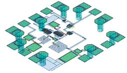
The microwave camera development consists of two main steps: a design of a prototype using thick film technology and commercially available components (as it is shown in Fig.1), and, finally, an integration of the microwave imaging system on chip using GaAs technology. The integration allows to significantly increase the operating frequency range, and, as a result, the spatial resolution. The design is performed using commercially available MMIC design software. To reduce the number of manufacturing runs the system is splitted up into functional units. Each unit is fabricated and tested separately. Finally, the functional units are gathered on the same wafer. Only the most critical units of the transmitter are placed on the separate wafer in order to keep high isolation level. The most important functional units are the ultra-wideband mixer, low noise amplifier (LNA) and switches.
 The designed ultrawideband mixer with integrated active high speed baluns and intermediate frequency combiner operates in a frequency range 0.1-8GHz. The device is manufactured on an advanced Gallium Arsenide (GaAs) process. The chip can be integrated directly into hybrid MICs. It operates from a single positive supply. The device is active double balanced mixer and can be driven by a single-ended LO source and requires only –4dBm of LO power. High common mode rejection ratio of the baluns provides exceptional balance in the circuit resulting in high port to port isolations. The mixer is optimized for high linearity, wide dynamic range downconverter application. All inputs and outputs are DC coupled. Broadband, integrated transformers on the RF and LO inputs provide singleended 50Ohm interfaces. The IF output is matched and usable for IF frequencies up to 3000MHz.
 The LNA is one of the most critical building blocks in the wideband microwave measurement unit. The main function of the LNA is to provide enough gain to overcome the noise of subsequent stages. The LNA consists of GaAs cascode amplifier with integrated output buffer (Fig 3). The chosen cascode configuration eliminates the bandwidth degradation due to Miller effect. It also provides high gain and very low noise performance. The LNA is designed to meet the demanding performance requirements of instrumentation applications. This amplifier can be used as a cascadable 50Ohm RF gain stage in order to achieve required sensitivity of the wideband measurement unit.
 The designed ultrawideband absorptive switches (Fig.4) with integrated drivers have high isolation and low insertion loss to 10GHz. The devices are absorptive (matched) switches with 50 O terminated shunt legs. They have on-board control logic, thus eliminating the need for external controlling circuitry. The switches operate using a positive control voltage of 0/+5 volts, and reququire a fixes positive supply for the control logic. Recent results of investigations available in published papers or by contact the researchers.
[Back to Research projects]