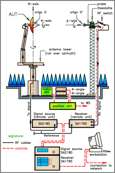
Mechanical system overview
Spherical near-field antenna testing requires that the near-field of the test antenna be sampled in amplitude, phase and polarisation in a regular grid on a spherical surface. This is accomplished in the TUD-ESA Facility by using a fixed probe and mounting the test antenna on a high-precision antenna positioner, as shown in the figure below.

Here, the intersection of the vertical and horizontal axes defines the centre of rotation and is thus the centre of a mathematically spherical surface, the 'measuring sphere'. This has radius, equal to the distance from the intersection point to a reference point in the probe, normally chosen in its aperture.
The probe, a conical horn, is mounted on the probe tower, shown to the right. This is positioned about 6m from the vertical axis of the antenna positioner. As can be seen from Figure, the test antenna transmits during the near-field scanning whilst the probe is receiving. If necessary, the direction of transmission can be reversed. The probe is dual-polarised and two orthogonal polarisation components are measured in amplitude and phase simultaneously at each measurement point on the measuring sphere.
Data collection and control
At each measurement point, the exact values of the two angular coordinates (rotation about the vertical and horizontal axes) are read by Inductosyn high-precision angular readouts and transmitted to an i386EX-based controller card. A similar controller card also controls the positioning of the tower and the collection of all RF-data, i.e. setting and reading of frequency and power level for the signal source, as well as receiver settings and readings. The controller acts as a preprocessor, relieving the Pentium computer of the time-critical parts of the measurements.
The computer assumes overall control of the measurement, according to a predefined 'test file'. It makes data reductions, scan-by-scan quality analysis, plots the curves and performs the spherical near-field to far-field transformation with probe correction, as concurrent tasks. The system is operated either from the main desktop computer of from a portable computer with radio-modem. The later is of especial help when mechanical alignment of the whole system is carried out.
Operation
Alignment. The measurement setup must be carefully aligned before the test antenna is mounted. To facilitate this important task, a theodolite is permanently mounted on the probe tower. Precision levels and optical mirrors are also used.
Probe calibration. Careful calibration of the probe is essential to take full advantage of the probe correction inherent in the transformation algorithm. Probe calibration is of particular importance for the measurement of gain, directivity and cross-polar patterns and for the calibration of standard gain horns. The probe is a dual-polarised conical horn excited by the TE11 mode in a circular waveguide. Due to the symmetry, full pattern information can be obtained for the probe by measuring from one of the two ports an E-plane pattern and an H-plane pattern in addition to the complex polarisation ratio on the axis. The spherical wave coefficients (probe coefficients) can now be calculated by the transformation software. However, before this is done, the data are corrected for the amplitude and phase difference between the two channels, as well as for on-axis cross-polarisation. Omission of the probe calibration is of course possible, but the transformation algorithm execution time is only slightly reduced. The measurement accuracy will then depend on having a sufficient distance between probe and test antenna. For this reason, probe correction is always a routine step in the measurements.
Mounting of test antenna. To ensure reproducible measurement conditions in terms of near-field amplitude and phase, the antenna positioner has a precision flange on its horizontal axis. Prior to the measurements each test antenna must be furnished with a matching mounting ring of similar precision. The test antenna is mounted such that its geometrical centre is as close as possible to the point of rotation. In this way, the antenna is enclosed in the smallest possible sphere centred at the rotation point - the 'minimum sphere' (of radius R) corresponding to that particular test antenna.
Near-field sampling. The electromagnetic field radiated from the antenna under test may be expressed as a finite sum of standard spherical vector modes (centred at the point of rotation) with unknown coefficients. The maximum mode order N that occurs in this sum is given by
N = 2pR / l + 10
where l is the wavelength and R is the radius of the minimum sphere defined above. The maximum permissible sampling increment in elevation and azimuth is p/N, according to the sampling theorem. Truncation of the measurements can sometimes be permitted, however, at the expense of reduced accuracy in the low intensity regions outside the main beam and first few sidelobes.
Near-Field to far-field transformation
The near-field to far-field transformation is carried out on the main computer using a special software based on program called "SNIFTD' from TICRA. This transformation includes also correction for the receiving pattern of the probe. The theoretical development of this correction was begun at DTU in 1970 and the first spherical near-field measurements with probe correction were carried out in 1977. The latest SNIFTD program has been written on the basis of previous experience with similar programs.
Usually, oversampling is used to reduce noise. Before the far-field transformation, the Fourier transform of each scan is computed during the measurements and only the significant harmonics are stored for later processing. After the measurement is completed, the elevation and azimuth components are normalised relative to each other and both are corrected for the ellipticity and tilt of the polarisation of the two probe ports.
In the SNIFTD program, a spherical wave expansion is calculated for the field radiated by the test antenna and this expansion is used to calculate the far-field. The field can, however, be evaluated at any distance by the program, and the near-field coupling to various probes can also be calculated. An integrated value of the radiated power is also calculated such that directivity can be determined in dBi.